This article was enhanced on 26-Oct-2014
“Design for Failure“, we hear this Slogan and importance of this philosophy in many cloud forums and conferences. Yet, every day many applications are Deployed/Architected on AWS without this point in mind. The reasons could be ranging from technical awareness of designing High availability(HA) Architectures to Cost of Operating a complex global HA setup in AWS. In this article, i have shared some of my prior experience on architecting High Availability systems on AWS avoiding and overcoming outages. I feel this small gesture will create HA awareness and help the strong AWS user community to build better solutions.
A typical Web App stack consists of DNS, Load Balancer, Web, App, Cache and Database layer. Now let us take this stack and see what are the major points that needs to be considered while building High Availability Architectures in AWS:
- Architecting High Availability in AWS
- High Availability @ Web/App tier
- High Availability @ Load balancing tier
- High Availability @ DNS tier
- High Availability @ Caching tier
- High Availability @ Database tier
- High Availability @ Search tier (in progress)
- High Availability @ NoSQL tier (in progress)
- High Availability @ Monitoring tier (in progress)
- High Availability @ Storage tier (in progress)
- Architecting High Availability across Amazon AZ’s
- Architecting High Availability across AWS Regions
- Architecting High Availability across Cloud and Hosting Providers/DC
High Availability @ Web/App tier
To avoid Single Point of Failure in the Web/App layer it is a common practice to launch the Web/App layer in minimum two or more EC2 instances. This is fault tolerant than the single EC2 instance design and offers better application stability. Usually the Web/App Servers are designed either with Stateless or State full models. Following are some of the common architecture patterns for HA in Web/App Layer in AWS Infra:

Following points needs to be considered while designing Highly Available and State full App Layer on AWS:
- Since AWS Infrastructure does not support Multicast protocol as of current date, the application layer software should synchronize data using Unicast TCP mechanism. Example: Java based App servers can use JGroups or Terracotta NAM or Hazel Cast to synchronize the data inside their cluster in AWS
- In case the Web/App servers are written on PHP, .Net , Python etc then all the user and session data can be stored on centralized systems ElastiCache -MemCached/Redis or Amazon DynamoDB. Deploy redundant ElastiCache Nodes in different Availability Zones for HA in AWS.
- ElasticIP based App Server switch will take ~120 seconds, not recommended for mission critical environments. It is advised to place the App servers under Load Balancers like Amazon ELB, HAProxy, Appcito etc for instant switch to healthy nodes.
- Session and User data can be stored on Database as well, i do not recommend this option. This can be followed as last option for software which are tightly built with databases.
- Uploaded User files and documents should be stored on common NFS or Gluster Storage Pool or Amazon S3. Lots of FUSE solutions are available in market which treats Amazon S3 as your disk, this provides good alternative for treating Amazon S3 as your disk. Note : Please carefully evaluate the latency requirements before treating Amazon S3 as Disk.
- Enable Session Sticky Policy in Amazon ELB or Reverse Proxies if Session Synchronization is not configured. This approach offers HA but not fail over transparency in App layer.
High Availability @ Load balancing tier
DNS and Load Balancing(LB) layer are the main entry points for a web application. There is no point in building sophisticated clusters, replications and heavy server farms in the Web/App and DB layer without building High Availability in the DNS/LB layer. If the LB is built with Single Point of Failure (SPOF) it will bring down the entire site during outage.
Following are some of the common architecture practices for building highly available Load Balancing Tier in AWS:
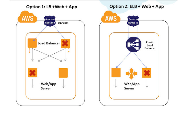
Practice 1)Use Amazon Elastic Load Balancers for the Load Balancing tier for HA. Amazon Elastic Load Balancing automatically distributes incoming application traffic across multiple Amazon EC2 instances. It enables you to achieve even greater fault tolerance in your applications, seamlessly providing the amount of load balancing capacity needed in response to incoming application traffic. It can handle thousands of concurrent connections easily and can elastically expand when more loads hit. ELB is an inherently fault tolerant building block and it can handle the failure in its layer automatically. When the load increases usually more EC2 Load balancer instances are automatically added in the ELB tier. This automatically avoids SPOF and overall site will be operational even if some LB EC2 instances in ELB tier have failed. Also Amazon ELB will detect the health of the underlying Web/App EC2 instances and will automatically route requests to the Healthy Web/App EC2 in case of failure. Amazon ELB can be configured with Round Robin in case the Web/App EC2 layer is Stateless and can be configured with Session Sticky for State full application layers. If the Session Synchronization is not done properly in the app layer then even Session Sticky balancing cannot save failover error pages and website failures.
To understand Amazon Elastic Load Balancing in detail:
|
Practice 2) Sometimes the application demands the need of :
- Sophisticated Load balancers with Cache feature (like Varnish)
- Load balancing Algorithms like least connection, Weighted
- Have heavy sudden load spikes
- Most of the request load generated from specific source IP range servers ( Example : Load Generated from System A IP to AWS)
- Require the Fixed IP address of the Load Balancer to registered
For all the above mentioned cases, having Amazon ELB in your Load Balancing tier will not be right choice. Hence for such scenarios we recommend usage of Software Load Balancers/Reverse Proxies like Nginx, HAProxy, Varnish, Zeus, Appcito etc in the Load balancing tier configured on EC2 instances. Such architecture can pose SPOF at the load balancing tier. To avoid this, usually it is recommended to have multiple Load Balancers in the LB tier. Even if a single Load balancer fails other load balancers are still operational and will take care of the user requests. Load Balancers like Zeus comes with inbuilt HA and LB Cluster Sync capability. For most use cases, inbuilt HA between LB is not needed and can be handled efficiently combining it with DNS RR load balancing technique. Let us see about this technique in detail below, before that there are certain points to be considered while architecting a robust LB tier in AWS:
- Multiple Nginx and HAProxy can be configured for HA in AWS, they can detect the health of the underlying Web/App EC2 instances and can automatically route requests to the Healthy Web/App EC2 instances
- Nginx and HAproxy can be configured with Round Robin algorithm in case the Web/App EC2 instances are Stateless and can be configured with Session Sticky for Stateful application servers. If the Session Synchronization is not done properly in the app layer then even Session Sticky balancing cannot save error pages.
- Scale out of Load Balancers is better than Scale UP in AWS. Scale out model inherently adds new LB’s into this tier avoiding SPOF. Scale out of Load balancers like Nginx, HAProxy requires custom scripts/templates to be developed. It is not recommended to use Amazon AutoScaling for this layer. Note : One problem with scaling out HAProxy is that there is no common single dashboard to control multiple scaled out HAProxy nodes.
- Load Balancers placed under the DNS needs the AWS Elastic IP to be attached. Since ElasticIP attach/Detach takes around ~120 seconds or more in some AWS regions, it is not advisable to run 2 LB’s switched between single ElasticIP model. It is recommended to run 2 or more LB EC2 instances attached individually with ElasticIP’s all running in active-active model under DNS/Route53.
- In event a Load Balancer EC2 has failed, we can detect this using CloudWatch or Nagios alerts and can manually or automatically launch another LB EC2 in few seconds ~ minutes in AWS for HA.
- Appcito offers load balancers as a Service. It is like Amazon ELB but with much more powerful features packed in the areas of Security, Performance, Access Controls for making IT ops life easier.
High Availability @ DNS Tier
HA at DNS Tier is an age old topic and been available for years. We used to architect HA solutions using Neustar -UltraDNS between AWS regions and DC before Amazon R53 became mature.
The "DNS" ,Amazon Route 53 is a highly available and scalable Domain Name System (DNS) web service. Route 53 effectively connects user requests to infrastructure running in Amazon Web Services (AWS) – such as an Amazon Elastic Compute Cloud (Amazon EC2) instance, an Amazon Elastic Load Balancer, or an Amazon Simple Storage Service (Amazon S3) bucket – and can also be used to route users to infrastructure outside of AWS. AWS Route 53 is AWS inherently fault tolerant building block and a Managed DNS service. Amazon Route53 can be configured using Console , API's to do DNS level Load Balancing.
Latency Based Routing and HA: LBR works by routing your customers to the AWS endpoint that provides the least latency. You can run applications on multiple AWS regions and LBR decides which region will give the fastest experience to the user based on actual performance measurements and directs them there. In event the primary region fails , LBR automatically directs the requests to alternative AWS region with next least latency. This automatic switch over provides inherent HA capability. DNA Failover can be configured with Active-Active Failover Using Amazon Route 53 Latency record sets
Refer http://harish11g.blogspot.in/2012/09/geo-distributed-route53-lbr-latency.html to know more in depth on this service
R53 Weighted Policy and HA: DNS Failover can be configured with Active-Active or Active-Passive Failover Using Amazon Route 53 Weighted mode, where the switching between infrastructure during outage takes place based on the weights configured. This is particularly useful when you are running a massive Geo distributed infrastructure on AWS.
DNS Failover can also be configured with Active-Passive Failover Using Amazon Route 53 Failover and Failover Alias Resource Record Sets. In this case, the secondary is passive and only when primary fails the secondary takes over. This Active-Passive Failover mode at Amazon R53 tier is useful for switching over to passive DR environments in event of outage.
High Availability @ Cache tier
ElastiCache Redis - Amazon ElastiCache Redis provides HA for persistent cache data. At times when your application grows rapidly some of them become so dependent on Cache tier with 100's of EC2 and TB of memory dedicated for caching. In event of such architectures, we cannot afford to lose the cache nodes easily in AWS. Amazon ElastiCache Redis has a HA solution in the form Read replica's and Slave promotion to Master. Refer the below articles to get in depth view for architecting HA on Cache tier :
Billion Messages - Art of Architecting scalable ElastiCache Redis tier
Architecting Highly Available ElastiCache Redis replication cluster in AWS VPC
High Availability @ Database tier
Data is the most valuable part of any application and designing High Availability for the Database tierr is the most critical priority in any Fault tolerant architecture. To avoid Single Point of Failure in the Database tier it is a common practice to launch the Multiple Database server's in Master-Slave replication or Cluster mode. Now let us see some of the common architecture practices and considerations for the same in AWS:

Master Slave Replication:
We can configure 1 MySQL EC2 as master and 1 or more MySQL EC2 as Slaves in this architecture. If they are deployed in AWS public cloud, then the Database Servers needs Elastic IP, if they are deployed in AWS Virtual Private Cloud, then we can work with internal VPC Network IP itself. Master and Slave will use Asynchronous replication of data between themselves in this mode. When the Master DB EC2 fails, using custom scripts we can promote one of the slave DB EC2 as master and ensure HA in this layer. We can have Master- Slave architecture running in Active-Active(A-A) or Active-Passive(A-P) HA mode. In A-A mode, all writes and immediate write-read txns should be done in Master DB EC2, independent reads are done from slave DB. In A-P mode all writes and reads should be done on master, only when master fails, slave is promoted and made active. It is recommended to use EBS backed AMI’s for all Database EC2 server instances for stability on disk level. For additional performance and data integrity we can configure MySQL EC2-EBS with various RAID levels as well in AWS.
MySQL NDBCluster:
We can configure 2 or more MySQL EC2 for SQLD + Data nodes and 1 MySQL EC2 as management node in this cluster architecture in AWS. Both the nodes in cluster will use Active Synchronous Data Replication between themselves. Write/Reads can be performed on both the nodes simultaneously. When one EC2 DB node in cluster fails other will be active to take the txn requests. If they are deployed in AWS public cloud, then the Database Servers needs Elastic IP, if they are deployed in AWS Virtual Private Cloud, then we can work on internal VPC Network IP itself. It is recommended to use EBS backed AMI’s for all Database EC2 server instances for stability on disk level. For additional performance and data integrity we can configure MySQL EC2 cluster-EBS with various RAID levels as well in AWS.
Multi-AZ RDS HA:
If we use Amazon RDS MySQL for the database layer, then we can configure 1 Master in Amazon AZ-1and 1 Hot Standby in another Amazon AZ-2 (will explain AZ concepts in detail in coming sections). We can additionally have multiple Read Replica Slaves attached to the RDS Master-Slave combination. For Additional HA, we can distribute RDS Read Replicas in Multiple AZ’s as well. RDS Master and Slave nodes will use Synchronous Data Replication between themselves. Read Replica Slaves will use asynchronous replication. When the RDS Master fails, RDS Hot Standby will get promoted automatically in minutes with the same endpoint URL. All writes and immediate write-read txns should be done in RDS Master, Independent reads can be done from RDS Read Replica’s. All RDS instances are currently built over EBS; RDS also offers point in time recovery and automated backups for stability. RDS can work inside Amazon VPC as well.
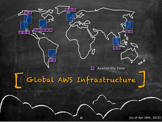
Architecting High Availability across AZ’s
Amazon Availability Zones are distinct physical locations having Low latency network connectivity between them inside the same region and are engineered to be insulated from failures from other AZ’s. They have Independent power, cooling, network and security. Following diagram illustrates the current distribution of Amazon AZ's(Purple boxes) inside a AWS Region(Blue boxes).
Most of the higher-level services, such as Amazon Simple Storage Service (S3), Amazon SimpleDB, Amazon Simple Queue Service (SQS), and Amazon Elastic Load Balancing (ELB), have been built with fault tolerance and high availability in mind. Services that provide basic infrastructure, such as Amazon Elastic Compute Cloud (EC2) and Amazon Elastic Block Store (EBS), provide specific features, such as availability zones, elastic IP addresses, and snapshots, that a fault-tolerant and highly available system must take advantage of and use correctly. Just moving a system into the AWS cloud doesn’t make it fault-tolerant or highly available; it is usually recommended to architect applications leveraging multiple availability zones of Amazon inside a region as best practice. Availability zones (AZs) are distinct geographical locations that are engineered to be insulated from failures in other AZs and come really handy during outages. By placing Amazon EC2 instances in multiple AZs, an application can be protected from failure or outages at a single location. Following diagram illustrates the various tiers (with sample software's) that should be architected with Multi-AZ concept.
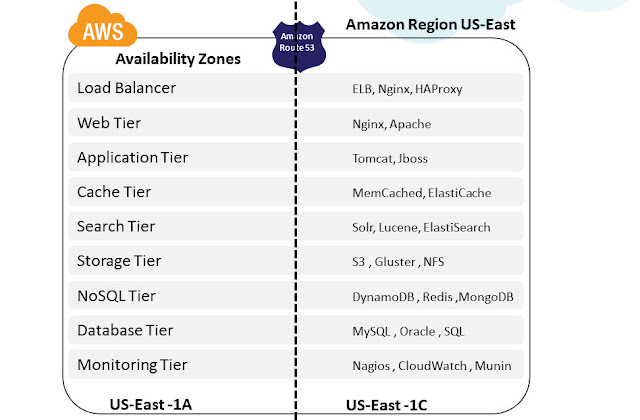
It is important to run independent application stacks in more than one AZ, either in the same region or in another region, so that if one zone fails, the application in the other zone can continue to run. When we design such a system, we will need a good understanding of zone dependencies.
Example:
A typical Web application consists of DNS, Load Balancer, Web, App, Cache and Database layer. All these tiers can be distributed and deployed to run on at least 2 or more availability zones inside an AWS region as described in the below architectures

Also most of the AWS building blocks are already built with Multi-AZ capability inherently. Architects and developers can use them in their Application architecture and leverage inbuilt HA capabilities.
Architecting High Availability using AWS Building Blocks
AWS offers infrastructure building blocks like
- Amazon S3 for Object and File storage
- Amazon CloudFront for CDN
- Amazon ELB for Load balancing
- Amazon AutoScaling for Scaling out EC2 automatically
- Amazon CloudWatch for Monitoring
- Amazon SNS and SQS for Messaging
as Web Services which developers and Architects can use in their App Architecture. These building blocks are inherently fault tolerant, robust and scalable in nature. They are in built with Multi-AZ capability for High availability. Example: S3 is designed to provide 99.999999999% durability and 99.99% availability of objects over a given year. It is designed to sustain the concurrent loss of data in two facilities. Applications architected using these building blocks can leverage the experience of Amazon engineers for building highly available systems in the form of simple API calls. Everyday amazon team is working internally on improving these building blocks by adding more features, making them robust and usable. These building blocks have their own advantages and limitations and have to be carefully used in the architecture based on the use case and fitment. Ideal usage of these building blocks drastically cuts down the cost of developing and maintaining a complex system infrastructure and helps the teams focus on the product rather than infrastructure.
Architecting High Availability across AWS Regions
AWS currently operates at 7 regions around the world and they are constantly expanding their infrastructure as I write this article. Following diagram illustrates their current regional infrastructure:
Architectures using Multiple AWS regions can be broadly classified into following categories:Cold, Warm, Hot Standby and Hot Active .
Since the Cold and Warm Architectures are majorly classified under DR strategy/practices with RTO and RPO’s, the Hot Standby and Hot Active architectures alone are dealt in this article context as High Availability Architectures for Multi-Region AWS.
In designing High Availability Architectures using Multiple AWS regions we need to address the following set of challenges:
- Workload Migration - ability to migrate our application environment across AWS regions
- Data Synch - ability to migrate real time copy of the data between the two or more regions
- Network Flow - ability to enable flow of network traffic between two or more regions
The Following diagram illustrates a sample AWS Multi Region HA architecture.
Now lets see how to address the above mentioned challenges:
Workload Migration: Amazon S3 or EBS backed AMI’s will operate only in regional scope inside AWS. We need to create the same AMI’s in another AWS region again for inter region HA architectures. Every time when a code deployment is made, applications need to synchronize the executable /jars/configuration files across the AWS regions. Use of Automated deployments like Puppet, Chef will make things easier for such ongoing deployment cases. Point to Note: In addition to AMI's ; Amazon EBS, ElasticIP’s etc also operate in AWS Regional scope.
Data Synch: Any complex system will have data distributed in variety of Data sources like Database, NoSQL, Caches and File Storage. Some of the preferred techniques which we recommend for AWS Multi Region Synch are:
- Database: MySQL Master-Slave replication, SQL Server 2012 HADR replication, SQL Server 2008 replication, Programmatic RDS replication
- File Storage: Gluster File Storage Replication, S3 Programmatic replication
- Cache: Since Cache replication across regions are too costly for many use cases, it is recommended to follow Cache warming inside every AWS Regions.
- Aspera for High Speed File Transfer
Since most these techniques are relying on Asynchronous Replication model, companies need to be aware of the Data loss, RPO and RTO they can incur in Architecting Multi Region AWS High Availability.
Network Flow: It is the ability to enable flow of network traffic between multiple AWS regions. Now let us see the points to consider in this:
- Since Amazon Elastic Load Balancers currently cannot transfer requests across AWS regions, it cannot be used for this Inter AWS Region High Availability Architecture
- Load Balancers/RP’s like Nginx or HAProxy deployed on EC2 on an AWS Region can do this, but during outages where an entire amazon region itself is affected, there are chances that the RP EC2’s are also affected and they cannot direct the requests to another AWS region effectively. This will lead to website failure.
- It is usually a recommended practice to achieve this User Network traffic re-direction at Managed DNS level. Using solutions like UltraDNS, Akamai or Route53 LBR (Latency based routing) we can shift or balance traffic between infrastructures hosted on different AWS regions.
- Using Amazon Route 53’s Latency Based Routing (LBR) feature, we can now have instances in several AWS regions and have requests from our end-users automatically routed to the region with the lowest latency. We need to enter the EC2 instance public IP, Elastic IP, or Elastic Load Balancer target in the Route 53 console for LBR to happen. This LBR feature can be used for designing GEO Distributed Infrastructures and High Availability Architectures across AWS regions. Behind the scenes, AWS is constantly gathering anonymous internet latency measurements and storing them in a number of Relational Database Service instances for processing. These measurements help them build large tables of comparative network latency from each AWS region to almost every internet network out there.
- Amazon ElasticIP’s are also not transferrable across AWS regions. FTP and other IP Based TCP endpoints used or hardcoded for App-to-App communication needs to be re-mapped or resolved using DNS accordingly. This is an important point to be considered in AWS Multi Region Deployments.
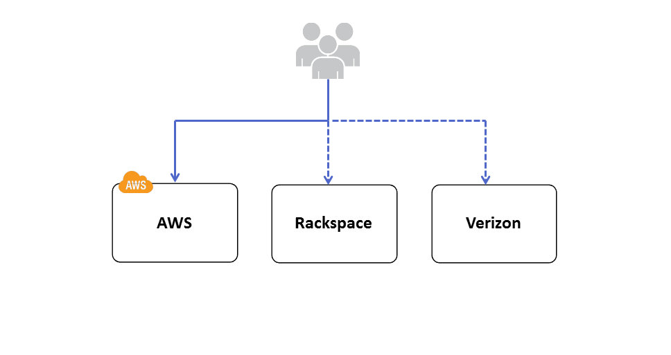
Architecting High Availability across Cloud and Hosting Providers/DC
I have seen many articles where people talk about Multi Cloud Provider Deployments for High availability. It is a very complex architecture use case and according to me following are some of the probable reasons why a company might evaluate this HA architecture:
- Large enterprises who already have invested heavily on their existing data centers/providers may want AWS to be their HA/DR cloud partner. Enterprises have Private clouds like Eucalyptus, Open Stack, Cloud Stack or vCloud installed in their existing DC and in event of DC outage, AWS is used as the HA/DR infrastructure. Eucalyptus is the most compatible providers of all these private clouds with AWS because of the API level compatibility. Many workloads can be easily integrated between AWS and Eucalyptus. Example: Let us imagine the enterprise has developed some automation scripts for Amazon EC2 using AWS API’s in Eucalyptus Private cloud infra ; it can be migrated to AWS infrastructure as well easily during HA situation; Whereas if the enterprise is using Open Stack or other Private Cloud providers in their DC they might have to redevelop/test/release this script. This effort might not be cost effective option to develop and maintain for complex systems.
- Companies which find their infrastructure not able to meet the Scalability/Elasticity demands will want AWS to be their primary cloud infra and existing DC/providers as their HA/DR.
- Companies which are not satisfied with the stability and robustness of their existing Public Cloud Providers may want Multi Cloud Provider deployments. This use case occurrence is very rare currently, may become central point when cloud dependencies and common standards emerge and mature in future.

Most of the considerations listed in above section of AWS Multi region HA will also apply in this Multi Cloud HA Architecture as well. In designing High Availability Architectures across Multiple Cloud providers/DC we need to consider the following points closely:
Data Synch: Usually this step will not be a big problem if the Data stores can be installed /deployed on Multiple Cloud Providers. Compatibility of Database software, Tools, utilities will matter a lot and if they can be feasibly installed, then this challenge can be effectively addressed in Multi Cloud High Availability.
Network Flow :
- The switch between Multiple Cloud providers should be usually done on the Managed DNS level – Akamai, Route53, UltraDNS etc. Since these solutions are not Cloud Provider REGION dependent, they can be used to effectively switch user network traffic between Cloud Providers/DC for High Availability.
- Fixed IP address can be provided by DC / Hosting providers whereas many Cloud Providers cannot give a Static Fixed IP address for a VM currently. This might be a major bottleneck while architecting HA between cloud providers.
- Many times VPN tunnel needs to be established between Cloud Providers /DC to migrate and synch sensitive data across clouds. There might be compatibility or feasibility problems on supporting this feature from some Cloud Providers. This needs to be carefully evaluated while architecting Multi Cloud High Availability Architectures.
Workload Migration:
- Amazon Machine Images are not compatible across Cloud providers; New VM images needs to be created again for Multiple Cloud Providers. This might lead to additional efforts and cost
- Complex Automation Scripts using Amazon API’s needs to Redeveloped for Other Cloud Providers using their own API’s. Some Cloud Providers will not even provide API based management, in such cases it will become Maintenance mess.
- OS , Software , NW Compatibility Issues needs to be carefully analyzed for feasibility before taking this Multi-Cloud HA decision
- Unified Management of Infrastructure will be a big problem in Multi Cloud HA scenario unless tools like RightScale are used for management